Monday, September 20, 2010

I needed to make a stand for my keyboards in order to accomodate a 30 key pedalboard. I have read on the Hauptwerk forum of members using a computer table from Ikea named Galant. I went to the Southampton Ikea and found out that one can purchase just the steel frame and adjustable legs for £40. This is what I bought. However when I got it back to my workshop it looked massive. I needed to achieve 125 cm clearance between the legs so I removed 14cm from the frame and MIG welded it back together.


Here is the finished fame complete with a quick coat of Hammerite.


First mockup in the workshop. The keystack has a prototype music stand in the picture below.  The most important thing about this modification is the resultant stand fits in the back of a Ford Focus.  The top is  50cm composite pine board from B&Q. 


The finished item. Quite pleased with the result. Just need the pedalboard.


Tuesday, September 07, 2010

Pistons!

X-Keys Stick works brilliantly but... It was a real pain to fit and I'm still not completely happy with its position. Also the buttons are too close together and the feel is so light that it is easy to press a piston by accident! Better for gaming than a virtual organ!


So the plan is to use momentary push switches from Miyama Miyama DS-412. These seem to be the correct dimensions and can be obtained very cheaply. In the UK you can get them from Mouser Electronics.


I plan to use an mpc32xrs MIDI controller from MIDI Boutique to scan the switches and send note-on / note-off messages to Hauptwerk.

I plan to use the following layout, 10 generals, 6 divisionals, pedal coupler and clear and set on the great. Thats 25 switches.

Swell       1 2 3 4 5     SW/PED   123456
Great   S   6 7 8 9 10    GR/PED   123456   C


Sunday, September 05, 2010

It had to be done, I bought another keyboard. I now have a 2 manual stack that conforms to the AGO 2.5" and 4.25" keyboard spacing. Below is the new case for the great keyboard. I wanted both keyboard cheeks to be the same height. So I made them both 2.5" in order to get the correct vertical spacing. Unfortunately this meant that the ply boards that support the keybeds are no longer flush with the bottom of the cheeks.  If I did it again, I'd make the keybed supports from 10mm ply.


Another thing I'd do differently, the X-Keys. Not that they don't work well, as the do. It's just their dimensions make it quite difficult to incorporate without encroaching on the lower keyboard. Discrete piston switches are the way to go.
I have also invested in a 15" touch screen monitor.


Next jobs, finish the wiring, a coat of varnish and get a pedal board.

Tuesday, August 24, 2010

Over the weekend I installed the X-Keys Stick and made a very rudimentary music stand. As Im using a Mac, I had to download ControllerMate to program the X-Keys Stick. This software is superb.  It allows real-time graphical configuration. I now have 10 pistons configured using the Haverhill Mini sample set. I'm very pleased with the result.


The picture below attempts to show the overhang of the swell keyboard and the relative position of the X-Keys Stick. This was the reason for removing the waterfall front of the keys. With the fronts in place, the key front to key front dimension would have to be at least 5.5" (4.25" being AGO standard) and the Stick would protrude too much. It was a tedious task, but I think it was worth it.

Next the expression pedal.

Sunday, August 22, 2010

Not cars this time, but virtual organs!

Ok, stop sniggering!


I've recently been playing a virtual organ called Hauptwerk. The remarkable thing about this piece of software is that it attempts to reproduce the actual sound of an organ by recording every pipe on every stop, a massive task. The sounding of each pipe is triggered by MIDI. The problem for me is to get suitable keyboards to trigger Hauptwerk. There are commercial products on the market but they are costly. So I decided to investigate less expensive options.

I initially used my trusty Yamaha NP30 piano, a MOTU MIDI interface and an Apple Mac Book with the free version of Hauptwerk. I was hooked. The reality of the sound is amazing.

Next job was to add a second manual / keyboard. I tried to get hold of some Fatar keybeds. However these proved to be very difficult to obtain. My second choice was an M-Audio Keystation 61es MIDI controller. These are readily available and inexpensive. There are a couple of problems going down this route. The first is that the keybed has "waterfall" piano style keys. This makes it very difficult to arrange the keyboards with appropriate spacing and allow for pistons. The second is the plastic case. This is ugly and has to go. I decided to with AGO (American Guild of Organists) spec as this is freely available on the internet.

So my plan was to add a Keystation 61es to the Yamaha NP30 and use an X-Keys Stick for pistons. A Yamaha FC7 pedal will be used for the swell. The FC7 can be connected directly to the M-Audio MIDI controller in place of the volume slider. I'm going for function rather than tradition.

Removal of the keybed from the plastic case is easy and has been well detailed on the Hauptwerk forum. However when I attempted to place the keybed on top of the NP30, it was obvious that the swell keybed would have to overhang the great in order to get close to an appropriate spacing. This was not going to happen with the waterfall fronts of the keybed. So out came the hacksaw!

Removal of the key front allows the top keyboard to overhang the lower whilst allowing space for the pistons. The X-Keys stick is 18mm thick. I did not want the piston buttons to protrude past the front of the upper keybed. 

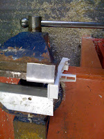
Removing the keys was the worst part. A screwdriver needs to be inserted as shown above to disengage a small plastic clip. 

Job done! The upper keybed can now overhang the lower. There is plenty of room for the X-Keys stick. The front to front dimension is about spot on. However the vertical spacing is about 10mm too great. Not much I can do about that.
I knocked up a case with basic wood from B and Q (Home Depot). Not a Vidarf but I did it in one day with no tools other than a jig saw! The piston rail is an 1" x 1" aluminium angle. If you look carefully, you'll see the upper keybed overhangs the lower by nearly 1". 
The X-Keys will arrive next week.


Next job, the music stand.

Tuesday, July 20, 2010

Many thanks to Paul Willetts for scanning the article below. It was a very good time to be in the Kit Car industry.


Thursday, June 17, 2010

Why no progress on the car? I've been working on the house! The Aga Little Wenlock wood burning stove has been installed on a South African granite hearthstone and the whole room redecorated. The colour scheme and blinds (yet to be fitted) were designed by Design House Winchester who also supplied the Little Greene paint.

Thanks to Mark Pyke of Dog House Designs for doing an excellent job on the floor. The floor is 21mm Hadlow Oak engineered boards with a 6mm wear layer. It is laid on Duralay Timbermate Excel underlay. 


We are gradually getting the living room back together.

CF100 coax has been run around the room concealed by the scotia for the cable TV.
Next the hall......

Thursday, June 03, 2010

Sylva website is down due to technical issues. For now, the content can be viewed here.

Urban Tune! No its not genre of popular music, it is a new type of ECU map for Triumph Bonneville / Thruxton / Scrambler.
The Triumph ECU inhibits start if the battery voltage drops below 12.6 Volts. Why? I have no idea! There is plenty of juice to start the engine. Anyway, what happens is when you try and start the bike it goes through its normal process, fuel pump screeches into life, warning lights come on, all good so far. When the start button is pressed, a relay clicks, the fuel pump stops and the warning lights go out. After about 5 seconds the pump and lights come back on.
A lot of contradictory information about this issue exists on the internet some suggesting bypassing the ECU start inhibit, others removing the left hand side panel and shorting out the solenoid with a coin! This is where "Urban Tune" enters the scene.
Some say that Urban Tune is a myth, others claim that it lowers the voltage threshold and others that it prevents the ECU from being powered on after the engine has stopped. So I called Three Cross where I bought the bike. Never heard of it! Must be a faulty relay, solenoid or starter, we'll pick the bike up on Monday. Hmm. I then phone up Triumph. To my delight I got to speak to someone knowledgeable. He confirmed that there is a Map called "Urban Tune" for my Bonnie. The only difference with this map is that it immediately powers down the ECU - according to Triumph. Anyway, I phoned 3X back again informing them that I'd contacted Triumph and that I wanted Urban Tune to be installed. They then admitted that it does exist and will install it FOC. Why not 'fess-up first time?

I must admit to being a bit disappointed. It seems that when Triumph converted the Bonnie from carbs to EFI, they located the ECU in the battery bay and installed a smaller battery! Then they program the ECU to inhibit start with a ludicrously high battery voltage threshold. Why, to protect the regulator / alternator? The Emerald ECUs I use in cars will operate down to 10 volts. Then to compound the issue it seems that the ECU remains powered up after the engine is stopped. Again why? I'll try "Urban Tune" and hope it restores faith in my Triumph.

The obvious solution is to put the bike on trickle charge to maintain its condition. However I don't have electricity in my garage! So I'm going to try an Oxford Solariser battery charger. I must admit I'm not convinced this will actually work. Watch this space......

Monday, May 17, 2010

I took the fuel tank out in order to complete the pipework. I also wrapped rubber around the pipes where they emerge from the tunnel. Installing the drivers side tunnel side was a real pain. Next time I'll panel up to the the dash before installing the floor. The rest of the panel would be easily fitted later.


Still not sure about the fog and reverse lights. Trouble is there are very few positions that meet IVA requirements that are not too close to the exhaust. 


I would have liked to run a piece of angle down the passenger footwell attached directly to the 1" tubes. However the tank is a very tight fit in this area. I settled for the solution below. The angle itself adds rigidity to the footwell and is bonded to the side panel with Stikaflex. 

Friday, May 14, 2010

My least favourite job is now complete! I'm quite pleased with the result; no glue on the leather cloth! The last item needing covering is the tunnel top. Would have that too but I've run out of glue. On the subject of glue, I've always used Evostick. Ok, it is messy but smells great! This time I used a spray contact adhesive from Halfords. It has worked very well.


Here's the dash with the VDO gauges fitted. If you look carefully you'll see the immobiliser receptacle just above the hazard light switch. Wiring it in will be one of the next jobs.  
It's all the little jobs that take up so much time. Below is the hand brake switch. The switch is a changeover micro switch from Maplin. 


Wednesday, May 12, 2010

Above is a wiring diagram for a Cobra A8510 Cat 2 immobiliser. I shall be fitting it soon!

Monday, May 10, 2010

I fitted the engine cover today. Thanks to Jeremy for the stainless lift-off hinges. The front edge of the cover is supported by a 15mm aluminium angle and the bare GRP edge is covered with tight 'n' fast. The lift-off hinges securely attach the cover whilst allowing it to be removed.

The picture below shows the rear bulkhead panels.  I've only covered the exposed tops of the panels. If you look carefully you can see the holes for the button head cap screws that will screw into the rivnuts. Not sure if I'd do this again as it is tricky to get everything lined up. A better compromise would be to rivet the panels on and fit access panels. 

Next time in the workshop,  cover the dash and fit the drivers side tunnel. Both jobs I have been dreading!
My least favourite job, sticking on leather cloth. The only redeeming feature is the smell of Evo Stick!

With the internal panels done, I covered the top of the rear bulkhead panels. The panels are rivnutted to the chassis so I can easily remove them for maintenance.
Next jobs on the list are fitting the engine cover, wiring the hand brake warning light switch and riveting on the  drivers tunnel side.

Tuesday, April 06, 2010

Emerald K3 and Tech Edge 2J1

Managed to spend some time in the workshop over the weekend. One of the pending jobs was to install a wideband lambda sensor. There were 3 options Innovate LC-1, DynoJet Wide Band 2 or Tech Edge 2J1.

The LC-1 has received some bad press recently, Emerald themselves are no longer recommending it even though it is the only product documented in the K3 manual. Another reason for not using the LC-1 is the messy installation. A 100 ohm resistor needs to be placed between the LC-1 out and K3 due to the sensitivity of the LC-1 output. Also the calibrate switch and status LED are remote from the unit itself requiring additional wiring and bracketry.

Next up, the DynoJet. Good kit, just too expensive.

That leaves the Tech Edge 2J1. This is very impressive kit at a great price.
Installation is a simple 4 wire hookup.


2J1 Power cable goes to a 5 amp ignition switched live and ground. When I make an ECU loom, I use a single ignition switched relay plugged into a holder that incorporates 3 fuses. I use one of these fused lives to power the lambda sensor and speedo sensor. The earth is connected directly to the battery along with the ECU.
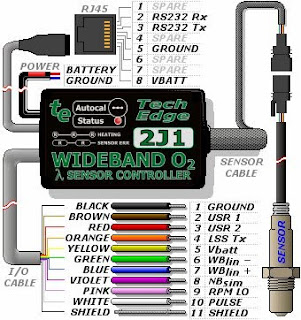
2J1 I/O cable provides 0 - 5 volt wideband output WBlin+ on the blue cable and ground reference for wideband output WBlin- on the green wire.  WBlin+ goes to any user defined analogue input. I chose AuxIn35. WBlin- connects to pin 30 along with the temp and throttle position sensors. It is interesting to note that WBlin- is an input into the J21. WBlin+ signal will generated with reference to WBlin-.

The Tech Edge website has a page describing the differential output of WBlin+. Note that the 2J1  does not have a GND SHUNT jumper. The default configuration is perfect for the Emerald K3. However if connecting the 2J1 to a single-ended logger or ECU, you'll have to link the black and green wires in the I/O cable.


Next task is to tell the Emerald K3 about the sensor. In the K3, AFR / Lambda Input Configuration Screen, set the input source and enter the values below. 

Input Voltage      AFR
0                  9
1                  11   
2                  13
3                  15
4                  17 
5                  19   

Stoic 14.7 AFR = 2.85 V  which is almost in the middle of the voltage range making the default a good compromise.

Tuesday, March 16, 2010

Sylva J15 on the front cover of Complete Kit Car out on 19th March.


Wednesday, February 10, 2010

Just seen a posting on the JPSC forum about fitting 13" wheels on an IRS Sylva Striker.
I was a little surprised at the pictures of a professionally modified car (not by Sylva) that has the rear suspension load passing through a spherical rod end shank in bending. The drawing below shows the arrangement. Rods ends should not be loaded in a way that tends to bend the threaded shank. The entire mass of car + bump load + weight transfer and brake torque will be fed through shank of the rod end in shear. OK you could install a joint large enough to take the load, but it would be far too big and heavy. Another thing to bear in mind, threads make very effective stress raisers! 


Below is how it is done on a Sylva Riot. The shock mount is as outboard as possible and a metalastic bush is used to resolve the spring load. The bending load is minimal and what little there is is fed through the wishbone itself.
If the compliance of a metalastic bush can not be tolerated, a spherical bearing (not rod end) could be used instead. This is OK as it has no shank. It is normally installed in a machined housing and retained with a circlip. The housing is welded to the wishbone in place of the ferrule that retains the metalastic bush.

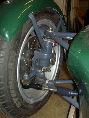
Sometimes this rule is broken. Below is a picture of the Riot front suspension. Braking torque is resolved through a rod end loaded in shear. Why is it OK to pass brake torque but not spring load through a rod end in this way? As mentioned above, spring load has many instantaneous components such as bump and weight transfer in addition to the mass of the car, the lower joint on a Riot's front suspension only has to resolve brake torque in shear and this is limited by the tyres. The rod end specified is well up to the job.