Wednesday, December 16, 2009

The Triumph has not left the garage since I rode it home last Saturday. Daily commuting duties have fallen to "The Trusty Steed", a Yamaha YBR 125. As I'm relying on it so much, I thought I'd show it some love.
A long overdue job was fitting new tyres. The original Cheng Shin tyres had about 1mm of tread left on the rear. Tyre sizes for the YBR are a bit strange, 90/90-18 on the back and 2.75-18 on the front. I ordered a set of Michelin Pilot Sportys from Micheldever Tyres. On Monday, I removed the wheels and had the tyres fitted. The difference is phenomenal. Anyone still using Cheng Shin tyres on their YBR 125 MUST change them for Michelin Pilot Sportys, they actually get warm and grip and they don't tramline  like the Chinese originals. 

 
The YBR 125 is built to a price. Components such as tyres, bulbs and mirrors are obviously low cost items that could benefit from upgrade. 
As I do most of my riding in the dark, I decided to to fit a halogen headlight bulb in place of the incandescent original . The bulb is 12v 35/35 watt with a BA20d fitting. I fitted a bulb made by Ring part number RMU417. They are available from AutoBulbsDirect for about £7. The difference is marked. The beam is much whiter and brighter. I had to realign the headlight as it was pointing too high with the new bulb.


Next, the mirrors and maybe a screen!

Sunday, December 06, 2009


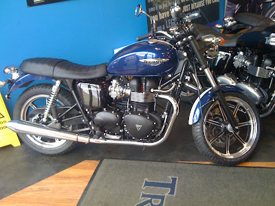
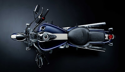
I've done it! Yesterday I  bought a new bike, a Triumph Bonneville. I could not resist the unique custom paint job. Its painted in Triumph Thunderbird Pacific Blue and Fusion White. Below is a picture of the Thunderbird that provided inspiration for the paint scheme.


I had a test ride at Three Cross Motorcycles and could not believe how easy it was to ride, far easier than the GS500 on which I took my test. The engine has oodles of torque ; no need to change down for roundabouts and it has a very progressive clutch. But the most impressive aspect of the bike was the handling. I was expecting a lumbering, heavy feel as this is a retro bike after all. However the bike tipped in very easily and felt very agile.

I have specified a few extras.
  • Tacho
  • Alarm / Immobiliser
  • Knee pads
  • Fork gaiters
  • Luggage rack
  • Center stand
  • Locking petrol cap - (why is this not standard?) 


I'll be keeping the YBR125 for rainy days when I need to commute.

Wednesday, November 11, 2009

Connecting a DynoJet Wide Band 2 to an Emerald K3 is very straightforward. You'll need a data acquisition cable (76950114) which is surprisingly optional on some kits.

Here's the wiring:-

WB 2               
violet            K3 analogue-in e.g. AuxIn35
white / violet    K3 pin 30, signal ground
red               3 amp ignition switched live
black             chassis ground
black / white     chassis ground 


Make sure that the pull-up resistor is not enabled for your selected analogue-in. This is done on the Input Channel Configuration screen. The 100 ohm buffer resistor, required for the Innovate LC1, is not required for the DynoJet Wide Band 2.

No configuration or calibration is required, the output is pre calibrated to (volts * 1.6) + 10 = AFR.

In the K3's AFR/Lambda Input Calibration screen set the input source to the analogue-in as used above and enter :-

Input Voltage   AFR
0               10
1               11.6 
2               13.2
3               14.8
4               16.4
5               18

After the ECU has been updated with these settings, it will be possible to read the current AFR from the live adjustments screen. It will also be possible to use the K3's adaptive mapping and closed-loop fueling capabilities.

Tuesday, November 10, 2009

My Riot has been neglected of late. I have recently sold my house in Christchurch. All of my superfluous paraphernalia is now stored in the workshop. Now we are in the process of moving again. This time 4 doors down the same street! This house has a garage! A rarity in Romsey.
Anyway the Riot. I'm thinking of changing the lambda sensor on my car yet again! Why? The Innovate LC1 is awkward to install and configure, has a very sensitive output and requires configuring and calibration.

My search for an alternative yielded products from TechEdge and DynoJet.


Reading various postings it would seem that both are superior to the Innovate product.
I have used DynoJet kit before and have been impressed so DynoJet it is.


Here are the benefits over the LC1.

Fixed configuration, no programming is required. The 0 - 5V analogue output is always (Volts * 1.6) + 10 = AFR.
Auto calibrating. No manual free-air calibration required.
Faster response.
Better packaging. No external push switch or LED. The sensor to controller cable can be cut to length.
Robust output. No need for an in-line buffer resistor.

With this in place, I should be able to map the low load sites as required for IVA and use adaptive mode for the rest.

Tuesday, October 06, 2009

Latest pictures of the J15 from Jeremy.


Thursday, September 24, 2009

Below is the column of grief! I spent ages cutting the steering lock from the column fitted to my car. Then I found out that IVA required either a mechanical or electronic immobiliser. The original IVA manual stated that electronic installations need to be certified. No way was I going to pay to have someone fit an immobiliser to the car so I decided to go the mechanical route. Trouble was finding a Sierra column with keys. Anyway I managed to obtain one. Trouble is the steering lock operates on the steering wheel. My Mountney boss has no provision for this. Then I find out that the requirement for certification has been dropped and I can install an electronic immobiliser! Anyone need a Sierra column with key?
This is work in progress. The headrests in this position would not pass IVA. There must be less than 50mm gap between the top of the seat and the bottom of the headrest.
I know some builders don't like exposed fixings on their cycle wings. However I prefer a solid mechanical attachment. I chose to drill and tap the stays.

Thursday, September 17, 2009

IVA, IVA!

2 things have been causing me grief. The first one is immobilisation, the second, headrests.

The IVA manual was updated on 29/06/2009. The requirement for an electronic immobiliser installation to be certified has been dropped. This is great news as I was going to fit a new steering column incorporating a working ignition switch and steering lock. It would have meant cutting a big hole in the dash and altering the wiring.

I have been looking at the Cobra 8510 Cat 2 immobiliser. It is a touch-key dual-circuit unit. I can install it on the front bulkhead isolating the fuel pump and starter. All for £30.

Next issue, headrests. One has to be careful when fitting headrests, the IVA manual has very specific requirements. The headrest size must be 85 mm wide each side of the vertical centre line of the seat and at least 100mm high. So what happens if your headrest is round like mine? The top of the headrest must be no less than 753mm above the seat squab and there must be no more than a 50mm gap between the top of the seat back and the bottom of the headrest. I have a set of the Sylva / Intatrim seats. Next time I'm the workshop I'll measure them up and let you know!

Thursday, September 10, 2009

On Monday I passed my Direct Access bike test, completing Module 1 and 2 at the Lee on the Solent test centre. Its been quite a journey; CBT, theory and hazard perception tests followed by Module 1 and Module 2.

There has been a lot written about the off-road Module 1 test, specifically the high-speed avoidance / swerve test. The issue is not with the swerve, but attaining the required 50kph. Anyone doing Direct Access will have no trouble at all. However I have witnessed poor souls attempting it on 125 bikes and really struggling. On a DAS bike, go round the corner in second, as soon as you exit the curve, give it full throttle. As soon as the timing device has been crossed, roll-off the throttle and perform the swerve. When the bike is upright, break hard, don't hang around the stop-box comes up very quickly. I did not attempt it on my 125 but I saw an instructor do it. He put the bike into third after the corner and revved the nuts off it. I was lucky as it was dry. No allowance is made for the increased braking distance in the wet, your front wheel must stop inside the box.

Thanks to Steve at ADT for being patient.

I must also mention that my sister Mary also did Direct Access with me. The first time she got on a a bike was 4 days before the test! She did incredibly well, managed to attain all Module 1 speeds but put her foot down in the U turn. She will pass Module 1 next Monday I'm sure. Respect!

Thursday, August 20, 2009


Good news from our friends "Down-Under". The Sylva Riot chassis has passed the torsional rigidity test required by some Australian states for road registration. The Riot chassis exceeds 4000N.m./degree stiffness. The photo above shows the test being performed.

Friday, June 26, 2009


Something has been troubling me. The pic above shows how I have plumbed my brake master cylinder, the port marked P (closest to the push-rod) is plumbed to the rear, the port marked S plumbed to the front. So the primary circuit is the rear and the secondary the front. I plumbed the rearmost port to the rear and foremost to the front for neatness!

As the cylinder has a parallel bore, I don't think it makes much difference. However, the IVA test now assess the efficiency of the secondary brake circuit. See below..

IVA manual Section 09E
The secondary brake performance must be at least 30%,(of the
CLW or DGW as determined to be the highest) for each half of the
split system.

I don't want the IVA tester seeing P cast on the cylinder and assuming that the primary circuit is the rear!

I'm not sure if the P and S circuits share the same push-rod or if they have their own with an interposing spring. If a single push-rod is shared, it really makes no difference. Without pulling the cylinder apart, I can't tell. If anyone has taken apart their master cylinder, let me know!

Anyway, I'm going to re-plumb the brakes. This is a pain as I really dislike bleeding brakes.
For a sanity check, I had a look for pics of Caterham master cylinder installations, this is the same cylinder used in the Riot. The pic below clearly shows the P port (closest to the push-rod) plumbed to the front.


Same for the AP 13/16" cylinder.

Some good news, I have ordered an Innovate LC-1 wideband lambda sensor. More about that soon I hope.

Tuesday, June 09, 2009

Latest pics from the Sylva factory.


Tuesday, May 26, 2009

It runs!

On Saturday afternoon I connected the battery from my Focus to the Riot's using jump leads. After a quick systems check I tried to start it. It did manage to start eventually but only on 2 and 3. I quick check using an old spark plug confirmed there was no spark on 1 and 4. I traced the problem back to the ECU connector where pin 25 had come adrift. I refitted and connector and tried again. This time 4 cylinders! There were 2 problems, no lambda output and no ICAV so I had to keep the engine running by opening the throttle. I called it a day as I had to get back to the house in order to prepare for a manic choir weekend!

Bank holiday Monday saw me back in the workshop for a couple of hours. I started the engine again and got it up to temperature. I wondered why the fan did not cut in? I does help if it is connected! This time with the fan connected, I let the engine get up to temp and to my relief, the fan did its job. While I was at the front of the car I finished the headlight wiring.

Back to the ICAV problem. I went to the idle control screen and confirmed that 2 wire PWM was configured. On saving the config the valve sprang into life making a huge racket! The default frequency was set to 40Hz. I upped this to 240Hz and it quietened down and the engine idled with no intervention from me.

I buzzed through all the connections for the lambda sensor. Everything was ok. Must be a duff sensor. I'm not too upset as this seems to be the only problem with the engine. I plan to replace it with a wideband sensor from Innovate . This will allow me to do adaptive mapping.

With the car running, I had to take it out for a spin! For the first time it moved under its own steam.

I am well pleased (116).

Next jobs, fit the cycle wings and finish wiring the lights.

Tuesday, May 19, 2009

Just returned from a fantastic weekend in Lincolnshire. We stayed with Jeremy and his family. The weather was extremely variable but we managed to find a dry spell to take the Riot out for a spin. It was the first time Sarah had experienced such a car. I drove first. I could tell she was a bit nervous. However things changed when we swapped seats. By the end of her drive, she was obviously enjoying the performance and grip of this fantastic little car.

Yesterday we went to the Sylva factory. I was very interested to see the new rear uprights Jeremy has had made for the Riot. They are fabricated in steel and use the Mk4 Fiesta bearing pack. Jeremy has moved the lower pickup points to allow the fitment of 13" wheels. The geometry has been changed to reduce scrub radius. In conjunction with new rear uprights, the front uprights are being changed to Triumph. This may seem a strange decision but they are proven, light and have good geometry; a much better proposition than the heavy, geometrically challenged Sierra alternative. Upper rocker arms will be retained. The lower wishbone will use a spherical rod end bearing instead of the traditional trunion.

These changes will allow Sylva to build a car with completely new components; no more dependency on ancient Capri / Escort / Mk2 Fiesta components. Also the use of Mk4 Fiesta driveshafts, bearings, hubs wheels and tyres means that a single donor kit is closer to reality.

Componenets that could be used from a single Fiesta 4 /5 Zetec donor:

Engine incl injection and all ancills, exhaust manifold, catalytic converter, wiring loom, ECU
Gearbox, driveshafts(modified?) and rear hubs
Fuel pump
Throttle, brake and clutch pedals
Clutch master cylinder
Wheels and tyres
Steering column (under investigation currently Sierra)

An excellent weekend. Many thanks to Jeremy, Stella and the rest of the family for being so hospitable.

Tuesday, May 12, 2009

Saturday was exciting! My Focus needed new tyres. Off I went to Micheldever Tyres and had 4 Toyos fitted in place of my trusty Michelin Pilots . I can no longer justify buying premium tyres as I don't do the mileage anymore. Whilst the wheels were off, it was obvious that I had no rear pads and the rear discs were very thin. This is strange as in the cars 83,000 miles, it has gone through 2 sets of rear pads and discs and one set of fronts. On Monday I had the car MOTd and new brakes fitted. A very expensive weekend!


I did manage some time in the workshop. The plan was to finish the ECU wiring, remove the plugs and spin the engine over to get some oil pressure. The wiring went ok. I had to make a judgement regarding the coil. The Haynes manual states that black / green = 1 & 4 and black / orange = 2 & 3. However on the coil connector, the black / green wire enters the coil pack next to the posts for 2 & 3 and black / orange 1 & 4. I went with my instinct assuming the Haynes manual incorrect.

Next job was the oil pressure sensor. This is located in a very awkward place just below the inlet manifold. As luck would have it, the original sensor was not screwed in very tightly and I removed it with mole grips. I have a combined VDO oil pressure sensor and warning light switch. It is impossible to get a spanner on the sensor to tighten it. So I coated the thread with Loctite lock 'n' seal and used the same mole grips to tighten.

With the ECU wiring complete and the dash connected, I verified that the guages and warning lights all worked. They did. I then pulled off the HT leads from the spark plugs in order to remove them. This is when my day did not go to plan! The chamber in the head where the plugs are located was full of rusty water! I spent the next couple of hours removing the O/S engine cover and cam cover and carefully removing the water and cleaning the head. I then removed the plugs. Luckily they came out easily even though they had been submerged for over a year! A final clean and I poured fresh oil on the cams and replaced the cam cover. I checked the oil level and with great trepidation I turned on the ignition, the oil pressure and alternator warning lights came on. Good start. I then pressed the starter button. After about 5 seconds of cranking, the oil light went out and pressure registered on the gauge. Result


Next I connected the ECU. I wanted to attach a laptop to it so I could calibrate the TPS and CLT sensors. The Emerald software is for Windows however my laptops are both Macs. To make matters worse, the ECU requires an RS232 serial port, my Macs only have USB. One of my laptops has VMware Fusion installed. I was sure this was not going to work but it did! I installed a serial to USB converter and the Emerald software and connected to the ECU. The first thing I did was backup the installed map. I then calibrated the CLT sensor as I'm using the OEM Ford one. To my relief, both air and coolant temp sensors read 15 degrees. I then calibrated the TPS. I was glad I had connected it the right way round! I then turned the engine over. RPM was being registered so I've got the CPS right too.

I installed a new set of plugs and called it a day.

Next time I'll finish the cooling plumbing and put some fuel in the tank and go for a start!

Wednesday, April 22, 2009

I’ve just been on the phone to VOSA regarding dual circuit brakes.
It would appear that an article in Total Kit Car has stated that spilt on dual circuit brakes must now be diagonal i.e. O/S front with N/S rear etc. instead of the more traditional front / rear split. The contentious paragraph is 09A section 4 which states,

"The vehicle must be fitted with a split (dual) circuit brake system with each part of the system operating on at least two wheels (one on each side), capable of operating in the event of a failure of the service brake or its power assistance."

I have just had it confirmed that the split can be front / rear or diagonal. Great news as my Riot is front / rear. However I was made aware of a new brake test that has been added to IVA that was not in SVA.

09E section 3
"The secondary brake performance must be at least 30%,(of the CLW or DGW as determined to be the highest) for each half of the split system."

DGW = Design Gross Weight
CLW = Calculated Laden Weight

The VOSA chap indicated that this new test may be difficult to achieve with a front / rear split. The test assesses the effectiveness of the least efficient circuit in the split. With a diagonal split you get one front and one rear brake per circuit – both circuits will have similar efficiencies. With front / rear, it will be the rear axle alone that will have to achieve 30%. OK so you could increase the efficiency of the rear but you still have to pass the dynamic lockup test.

In conclusion, front / rear split is ok but you’ll have to make sure the rear axle makes 30% efficiency without locking up before the front. A possible solution could be to ensure the design weights you supply are as low as possible. More later.

Monday, April 20, 2009


My Riot has a new home! I have just taken on a workshop in Nursling, just to the north of Southampton. I'll be installing the rest of my equipment in he next couple of weeks.

SpringWorks is the name of my new company. 4 days a week I do IT consulting specializing in Java, JEE, Spring (hence the name) and Flex. The rest of the week, I can undertake work on kit cars specializing in the Sylva Marque.

SpringWorks Ltd
Unit H
Church Farm Business Centre
Nursling
SO16 0YB
Tel: 077 6654 2698
Email: paul@springworks.eu.com

Sunday, February 15, 2009


Monday the 9th was probably the wettest day of the year, the day I took my CBT. Great! After 2 hours of riding in the pouring rain, I was eventually given my DL196. The following day I bought a 2008 Yamaha YBR125. I'm ready for my daily commute now.

The Riot, well not much has happened. I have fitted an air filter, fitted a new oil filter and filled it up with oil and finished the cooling plumbing. The dash wiring is done. I just need a whole day on the engine loom and we should be ready for a start!

Thursday, January 29, 2009


I've spent the last couple of days working on the wiring loom and dash.
I fitted the VDO instruments and switches including a Hella hazard switch as it has the requisite 7 connectors, a Lucas 2 way ignition switch and a push button starter. Delta rocker switches are used for head / sidelights and fog lights. I have not sorted the horn or dip / main switches yet.

Is this why people buy a Digidash? I was tempted but I feel the Riot is better suited to the more traditional discrete instruments even though they are an utter pain to wire up.

Next time in the garage I'll be tackling the engine bay including the ECU.

Wednesday, January 21, 2009

I really struggled yesterday. I could not find a suitable position for the fuse boxes, relays and flasher unit. I finally opted to mount them under the steering column cover. OK, I realize that I'll have to remove 6 bolts to change a fuse, however I'm hoping not to be doing that too often!

To make matters worse, 2 wires came adrift from the fuse boxes. It took me a while to work out how the fuse boxes come apart. I contacted Premier Wiring (new phone number 0131 554 0099) and they sent me some new crimp connectors.

You can also just make out at the top of the picture the 2 pieces of the loom coming through the bulkhead. Again a struggled to find an elegant solution for the cable routing.

Sunday, January 18, 2009

I had originally sourced a header tank from a Rover 214, however I wasn't too happy with its size.
Hunting around my local scrapyard, I found this header tank from a VW Golf. It fits very nicely in the space available. I am going to relocate the air filter. You can see the big 70mm elbow just below the header tank.

Below is the filter I'm considering. C7010 is the most compact filter with a 71 mm O/D neck.


I bought a loom from Premier, however the first thing I did was to pull it apart! I've removed the wiper, washer and heater wiring and significantly shortened the dash loom. I'm going to have to add wires for the fuel pump and fan relays, they are controlled by the ECU mounted in the rear.

Tuesday, January 06, 2009

Cracking the Colour Code!

OK a bit of an excuse! I haven't done any real work on the car over the Christmas period, too much singing!

What I have done is work out the colour coding for the Focus ECU loom. I tried Googling but have been unsuccessful finding the required information. So here goes!

My engine was supplied with the remnants of the Focus engine loom; it had been unceremoniously chopped off at the ECU. I want to use as many of the connectors and cables as possible. I have an Emerald K3 ECU, so I need to connect injectors, coil, idle air valve (IACV), coolant, air temp crank position (CPS), lambda and throttle position sensors (TPS), fuel pump, fan and tacho.

In general Ford looms use black wires for earth and brown for power. However this does not hold true for the engine loom.

Please be aware the the colours below are for a 1.6 Focus loom. Zetec powered Fiesta looms are similar but not the same.

Green / blue cable is an ignition switched live. It powers the injectors, coil, lambda heater and IACV.
Black cables with a trace colour are ECU controlled switched earths. These trigger the coils, injectors and IACV.
Brown wires with a trace colour are sensor grounds. These are for sensors that require an accurate ECU derived ground reference; connecting to the chassis won't do. These include the temperature sensors, TPS, CPS and lambda sensors.
White wires, solid or with a trace colour, carry signals from the temp sensors, TPS, CPS and lambda sensors.

OK so that's the high-level overview, now for the details.

Injectors
black / white cylinder 1 ECU 24
black / orange cylinder 4 ECU 24
black / yellow cylinder 2 ECU 23
black / blue cylinder 3 ECU 23
green / blue ignition +12v connect to power relay

Coil
black / green cylinders 1 and 4 ECU 25
black / orange cylinders 2 and 3 ECU 5 (watch out same as inj 4)
green / blue ignition +12v connect to power relay
(Not sure if the above is correct. I have switched 25 and 5)

Idle Air Control Valve
black / yellow switched earth ECU 3 (watch out same as inj 2)
green / blue ignition +12v connect to power relay

Coolant Temp
white / violet signal ECU 33
brown / white sensor ground ECU 30

Air Temp
signal ECU 16
sensor ground ECU 30
I don't have cable colours for this as the air temp sensor is in the Temperature and Manifold Absolute Pressure Sensor (TMAP) sensor in the Focus. Strangely the TMAP sensor is not mentioned in the Focus Haynes manual. Anyway I plan to use it. The K3 allows the temp sensors to be configured. It seems that Ford have standardised on the calibration of their temp sensors (air and coolant are the same).

0c = 94k ohms
50c = 11k ohms
100c = 2.2K ohms

I have not tried the above yet but will report back along with wire colours.

Throttle Position Sensor
brown / red sensor ground ECU 30
yellow +5v supply ECU 9
white 0 - 5v signal ECU 8

Crank Position Sensor
cable screen ECU 29 - one end only
white / red signal ECU 31
brown / red sensor ground ECU 32
Use shielded twisted pair microphone cable if not using Ford cable.

Lambda (Narrow)
white signal ECU 7
brown sensor earth ECU 18
green / blue relay controled +12v heater supply
black / yellow heater ground - connect to chassis

ECU pin 36 can be used as a switched ground to control the heater relay.
For wideband wiring see K3 manual.

Fan
ECU 6 switched earth

Fuel Pump
ECU 20 switched earth

Tacho
ECU 12 0-12v pulse

I think that's it! Please email me or leave a comment if I have made any errors.
Once I have tested the above, I'll post a page on the Sylva web site.